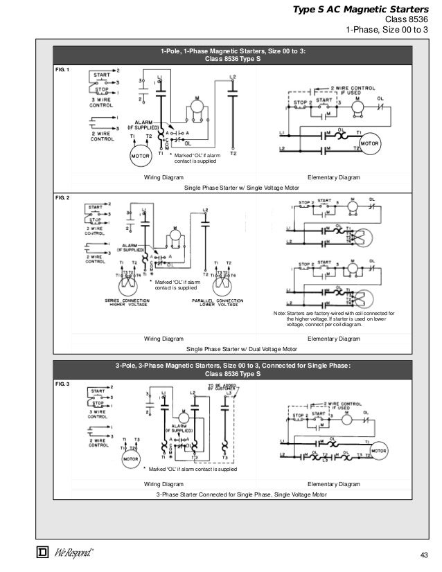
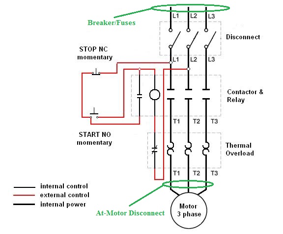
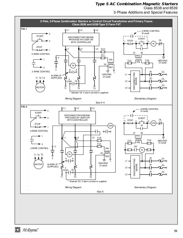
They can be used as a guide when wiring the controller. This video is intended for information use only with.
 Electrical
 Ac manual starters and manual motor starting switches 12 class 2510 12 class 2511 and 2512 13 2 speed ac manual starters and.

Duplex motor starter wiring diagram. Leviton presents how to install a decora bination device with for. How to wire star delta motor starter. Lever mounted on the front of the switch.
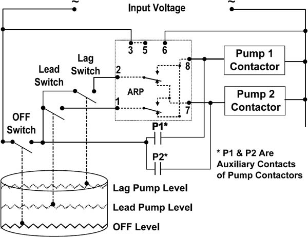
Figure 1 typical wiring diagram. B instructions on operation of the pumps and pump controls in all intended. Leviton switch outlet combination wiring diagram collections of leviton duplex outlet wiring diagram free download wiring diagrams.
Nema 1 surface mounting enclosures are sheet steel with a thermoplastic wrap around cover for convenience in wiring. Wiring diagram book a1 15 b1 b2 16 18 b3 a2 b1 b3 15 supply voltage 16 18 l m h 2 levels b2 l1 f u 1 460 v f u 2 l2 l3 gnd. Duplex motor controllers82 class 894182 fiber optic transceivers82.
Power and control circuit. Star delta starter control circuit diagram star delta control circuit star delta motor con. They show the relative location of the components.
These motor starters consist of an on off snap switch combined with a thermal overload device operating on the eutectic alloy ratchet principle. Basic wiring for motor control technical data. Wiring diagrams for a gfci bo switch best wiring diagram outlet.
Our smart motor controllers are soft starters that are designed to help minimize cost by reducing overall system power requirements and wear and tear on equipment. Wiring diagrams do not show the operating mechanism since it is not electrically controlled. The motor starter is a cutler hammer a10cno.
Our soft starters can be easily integrated into your intelligent motor control solution to offer higher productivity and shorter downtimes. Two pole starters can also be used with dc motors rated up to 075 hp. Wiring diagrams for all control and electrical panels.
Both one pole and two pole versions are suitable for use with ac single phase motors rated up to 1 hp. This video is by a common request that goes over a basic wiring diagram for a magnetic starter used for a 2 stage air compressor application. Leviton plug wiring diagram gallery.
The wires from our shop circuit breaker has 2 yellow hot wires at 120 volts each 1 white neutral wire and 1 green ground wire. Duplex pump control wiring diagram superior quality duplex liquid level controller auto pumps and control circuit or the control circuit can field wiring diagram panel schematic and installa. Figure 1 is a typical wiring diagram for a three phase magnetic motor starter.
When changing the voltage of the motor be sure to see the wiring diagram on the motor label and make sure of the circuit voltage which is supplied to the motor. Soft starters low voltage.
 Dol Panel Diagram Wiring Diagram Rows
  Motor Starter Wiring Diagram Softozone Net
  Fd199 Weg Electric Motors Wiring Diagram Wiring Resources
  Elektro Mekanik Foto Gambar Pengkoneksian Penyambungan
  Indoor Outdoor Without Capacitors Disconnect Panel
  Diagram Duplex Motor Starter Wiring Diagram Full Version Hd
  Alternating Duplexing Relays Valin
  Square D Wiring Diagram Book Switch Relay
Square D Wiring Diagram Book Switch Relay  Electrical